I've rebored the PTFE to remove the notches I previously made on the inside of the barrel. It now has a diameter of 5.5mm and is completely smooth again. I've remounted it on the extruder base and attached the nozzle.
I've also rebuilt the original nichrome wire heater wrapped around the nozzle, just in case the new heater block I've made is causing the problem with molten PLA backing up into the PTFE barrel.
The heater part works fine, unfortunately the nozzle is still filling with molten PLA. Since it never used to do this before the original catastrophic failure of the PTFE barrel that this is the cause. I'll need to make a new barrel.
The problem is I don't have a lathe, so do I spend $95 on the techshop lathe class so I can use their lathes and then pay $125 for the one month membership, or pay ~$500 for a mini-lathe for my workshop.
I'd like a lathe, but I doubt I'd use it again after this. Perhaps Santa will bring me one?
Friday, December 10, 2010
Sunday, December 5, 2010
Extruder Problems Continue
After rebuilding the extruder and running some test prints the extruder is still having problems. After about 10-minutes of printing the filament stalled again. The PTFE of the nozzle had backed up with molten PLA again.
I think I'll try two more things tomorrow. Firstly, I'll rebuild the extruder with the original nichrome wire heater - perhaps the block heater is more suited to the new style extruder where the brass doesn't get inserted as far into the PTFE. I think that perhaps because the brass nozzle extends into the PTFE 15mm or so, it is transferring heat further up the insulator than with the new style extruder.
Secondly, I'll try boring out the PTFE insulator. There is a slight notch on the inside where the drill slipped when I was drilling out molten PLA previously. This notch appears to be catching the molten PLA, which could be causing the feed problems. This will increase the internal bore diameter slightly which hopefully won't cause any problems.
If none of this works, I'll be rdering some PTFE and joining TechShop and using their lathes.
Saturday, December 4, 2010
Building the Block Heater
As part of rebuilding the extruder I thought it would be a good idea to build the block style heater, rather than than the original heater. I made a couple of modifications to the build, we'll see how they work out.
I followed the mechanical drawings and plans on the RepRap Site. It did require me to buy a drill press, metric drills and a metric tap and die set, but I do enjoy having new power tools!
I used a 3/8" ultra-machinable brass bar from McMaster. Cutting and machining it was fairly straightforward. The new drills and drill press did their job well.
I haven't tapped anything since I was at school, but the technique came back quite quickly. A quick test fit showed that everything went together easily.
I used 1mm PTFE tubing I found at Frys to insulate the leads for the thermistor.
To increase the thermal conduction between the thermistor and the resistor and the block I used Biostar Nano Diamond thermal grease. It is good up to 240c and is an electrical insulator. I filled the thermistor hole with the grease before pushing it home. The resistor was coated with the grease before sliding it in to its hole.
While I was shopping for the fire cement I found a Rutland caulk good to 600F at Ace. It doesn't require heat curing and is flexible. I'll give it a try and see how it works out. It was a little messy to apply but should be better than fire cement.
After wiring it up and waiting for it to cure first tests appeared to be promising. It heated up quickly to the specified temperatures.
First tests with filament did not go so well. The filament did not feed very well and the output from the nozzle curled up! - Not sure why?
Then catastrophe struck again, the nozzle appeared to seize up. It appeared that molten PLA had backed up the PTFE and solidified.
It was another late night dismantling the nozzle and cleaning it out and drilling out the solidified PLA out of the PTFE. After it was all clean I checked the nozzle opening in case there was something stuck in there causing the curling.
Using another thermistor as a temperature probe inside the nozzle it I checked the temperature inside the nozzle. There appears to be a significant difference between the block temperature and the nozzle temperature. The block has to register between 250 - 260c for the internal temperature of the nozzle to register between 205 - 220c. This may have been the cause of the feed problems. At a block temperature of 220c the internal nozzle temperature was only at 185c.
Cranking the temperature up to 260c and trying some manual filament feed tests shows this temperature setting was much better. Tomorrow I'll try rebuilding it completely and testing it with the motor feed.
 |
| The basic components of a block heater. |
I used a 3/8" ultra-machinable brass bar from McMaster. Cutting and machining it was fairly straightforward. The new drills and drill press did their job well.
I haven't tapped anything since I was at school, but the technique came back quite quickly. A quick test fit showed that everything went together easily.
I used 1mm PTFE tubing I found at Frys to insulate the leads for the thermistor.
To increase the thermal conduction between the thermistor and the resistor and the block I used Biostar Nano Diamond thermal grease. It is good up to 240c and is an electrical insulator. I filled the thermistor hole with the grease before pushing it home. The resistor was coated with the grease before sliding it in to its hole.
 |
| With all the parts inserted. |
After wiring it up and waiting for it to cure first tests appeared to be promising. It heated up quickly to the specified temperatures.
First tests with filament did not go so well. The filament did not feed very well and the output from the nozzle curled up! - Not sure why?
Then catastrophe struck again, the nozzle appeared to seize up. It appeared that molten PLA had backed up the PTFE and solidified.
It was another late night dismantling the nozzle and cleaning it out and drilling out the solidified PLA out of the PTFE. After it was all clean I checked the nozzle opening in case there was something stuck in there causing the curling.
 |
| Complete and back on the extruder. Note the new sprung loaded mech. |
Using another thermistor as a temperature probe inside the nozzle it I checked the temperature inside the nozzle. There appears to be a significant difference between the block temperature and the nozzle temperature. The block has to register between 250 - 260c for the internal temperature of the nozzle to register between 205 - 220c. This may have been the cause of the feed problems. At a block temperature of 220c the internal nozzle temperature was only at 185c.
Cranking the temperature up to 260c and trying some manual filament feed tests shows this temperature setting was much better. Tomorrow I'll try rebuilding it completely and testing it with the motor feed.
Sunday, November 28, 2010
Fixing the Extruder
It looks like it might be possible to salvage my current extruder. I have successfully managed to clean out the brass nozzle by heating it up with a butane torch and pushing the stuck filament through with a drill. It's currently going through a final cleaning by spending the night in a glass full of acetone.
The PTFE insulator was a bit tougher. Due to my earlier problems with the hot-end, it is well glued into the extruder base and it is half-full of PLA that followed the nozzle down as it was pushed out. I managed to get this clear by screwing the nozzle back in as far as it would go then heating it with the torch, then screwing it in some more. This pushed the excess into the nozzle and I could pull it all out with the nozzle.
The nozzle appears to fit still, so I'm not sure why it decided to drop out during the print process, unless the PTFE deformed. I plan to wrap the nozzle in a few layers of PTFE tape and screw it back in, then re-build the whole extruder again. But first, I need a new thermistor, it got destroyed whilst trying to clean the nozzle up. I'll check Fry's tomorrow or place an order with Digikey.
However, I doubt the extruder will last much longer after it is rebuilt so a complete new extruder is on order from Mendel-Parts with the PEEK style nozzle. However, judging by the latest update message from Camiel on his site, I doubt I'll see it before February. Hopefully his assistant is alright, it sounds like they had quite a week!
I also plan on building the brass block style heater instead of the wound wire version. It will give me something to do while I can't print. It's also a great excuse to buy a drill-press. I found that the kapton tape on my current extruder would melt gunk into the objects that I was printing.
I'm wondering if this is an indication the extruder was getting too hot? When I rebuild it I'll put the thermistor slightly further up the nozzle, rather than close to the tip.
Fingers crossed I can at least print something for the next few weeks, otherwise I'll be writing applications or playing with CAD packages.
Saturday, November 27, 2010
Extruder Problems
The most frustrating thing about my Mendel is my extruder. I've had lots of problems with it since I completed the build. It's Adrian's Geared extruder with the hot-end epoxied into the base rather than held in by a PEEK block.
The first problem that I had was caused by my wimpy stepper motors getting too hot. The excess heat caused both the extruder base and the X-carriage to distort. This has since caused all sorts of meshing problems for the extruder gears as they no longer line up.
The second problem that I had was the hot-end dropped out completely while working on a print. Frustrating, but easily fixed by liberal application of more epoxy.
Today I resolved to fix the meshing issue which causes the gears to skip, resulting in poor extrusion. I completely dismantled the extruder body to fix the alignment between the motor mounting plate and the extruder base. After they had become distorted they developed a slight kink in both parts, and whenever I tried to align the gears the parts would prefer to slip back to align with the kink.
The solution was to file the kink flat on both parts and make up for the missing material with an M4 washer. I also found that the excess heat had partially closed the bolt slots on the base, preventing the bolts from sliding as needed. After opening these back up again I could position the motor so that both gears engaged successfully.
Several tests showed that everything was working perfectly, so back to printing. In this case some new frame vertex with feet, since my Z-axis pulleys stand a little proud for the current feet to handle.
Unfortunately, half-way through the print another extruder problem developed. The threaded brass insert that makes up the extruder was pushed out of the PTFE block. Shifting it down about 5mm and leaking molten PLA out over the nozzle.
I'm not sure if I can salvage this extruder hot end, I might need to build a new one using the PEEK block to attach the nozzle to the PTFE. This should solve at least two of the extruder problems I've experienced in the past two weeks. It wouldn't be so bad if I've been churning out hundreds of Mendel parts, but I've only managed to print a couple of small objects and two vertex's. Reading other RepRappers blogs, I can see that others have far more success with their extruder than I do with mine.
Oh well, time to research new hot-ends!
The first problem that I had was caused by my wimpy stepper motors getting too hot. The excess heat caused both the extruder base and the X-carriage to distort. This has since caused all sorts of meshing problems for the extruder gears as they no longer line up.
The second problem that I had was the hot-end dropped out completely while working on a print. Frustrating, but easily fixed by liberal application of more epoxy.
Today I resolved to fix the meshing issue which causes the gears to skip, resulting in poor extrusion. I completely dismantled the extruder body to fix the alignment between the motor mounting plate and the extruder base. After they had become distorted they developed a slight kink in both parts, and whenever I tried to align the gears the parts would prefer to slip back to align with the kink.
 |
| Note the kink in both parts and the buried washer. |
Several tests showed that everything was working perfectly, so back to printing. In this case some new frame vertex with feet, since my Z-axis pulleys stand a little proud for the current feet to handle.
 |
| Previously the wires were flush with the PTFE. |
I'm not sure if I can salvage this extruder hot end, I might need to build a new one using the PEEK block to attach the nozzle to the PTFE. This should solve at least two of the extruder problems I've experienced in the past two weeks. It wouldn't be so bad if I've been churning out hundreds of Mendel parts, but I've only managed to print a couple of small objects and two vertex's. Reading other RepRappers blogs, I can see that others have far more success with their extruder than I do with mine.
Oh well, time to research new hot-ends!
Friday, November 26, 2010
What Causes the Warts?
 |
| Printing with Warts |
At first I thought these were caused by the oozy nature of PLA. Just turn on the extruder to heat and without running the motor molten PLA will ooze out of the extruder, seemingly forever.
However, I was determined to stop it from happening. I started playing with both Oozebane and retraction speeds and distances in Skeinforge to no avail. These settings only affect the end of a thread, these warts appear in the middle of a thread run.
I started to watch my printer more closely to see what was causing them. It became apparent that the warts are caused when the printer stops for a fraction of a second and PLA oozes out on to the print. Why was my printer pausing?
I reviewed the firmware code to see if I could spot the cause. It's complex as there are so lines of code for other printer configurations in the firmware that you get lead down a particular path only to discover that piece of code isn't compiled into your specific printer. Nothing obvious jumped out.
Then I wondered if the GCode buffer was running dry so I started to review the RepSnapper log files. The timing information in them wasn't sufficient to spot buffer under-run, so I switched to PortMon, my favorite serial monitor. It didn't appear that there was any noticeable delays in getting the GCodes on chip at a baud rate of 19,200. A few quick calculations confirmed this.
I did note two things in the log file though. The first was there were loads of retransmissions. Mainly caused by Skeinforge generating M101 and M103 extruder commands, which aren't used by Mendel. I'm not sure how to prevent Skeinforge from generating these, if anyone knows let me know. When the Gen6 electronics receives these commands it responds with a 'Huh - I don't know what this is' and then it asks for the last packet before that to be resent. Perhaps this was causing the buffers to run dry as the firmware flushed the previous commands? So I wrote a quick Python script to remove the duff M10x commands and retried the prints. They were still warty.
 |
| Wart-less Test Print |
From now on, I'll switch off the temperature monitoring in RepSnapper, but I'll still continue to run my pre-processor script as it prevents thousands of re-transmissions per print. I've also added the ability to substitute the Skeinforge start-up code with my preferred start-up GCodes.
 |
| Before and After |
Tuning Skeinforge
Skeinforge has *lots* of parameters to set and not much information on what they all do. To help me set my version up I found the following page very useful (although some of the parameters have changed name or no longer exist) Skeinforge Wiki.
In the end I went with the default parameters for PLA with the following changes.
Feed Rate = 40mm/s
Flow Rate = 57.6
Retraction Speed = 250
Distance = 30mm
Extra = -10mm
The last 3 settings help with the blobbing that you get at the end of each thread by sucking the excess filament back into the nozzle by momentarily retracting the filament. I've found PLA to be very oozy.
I found the best page to help me set up the feed rate and flow rate was this one from Tony @rapman3. Since I'm using a stepper based extruder the flow rate setting, which appears to be a PWM control value was a bit meaningless, however, I followed Tony's instructions to set up the deposited filament width to 0.72mm with a height of 0.4mm by varying the Flow Rate setting for the specified Feed Rate setting. By trial and error I found that the setting for a feed rate of 16mm/s (bed speed) required a flow rate of 23.
At 16mm/s, this printed too slowly and I know that the Mendel can print much faster, so I upped it to 40mm/s and found that the Flow Rate scaled in a near linear fashion. To test the various parameters, I used Tony's approach of printing a single filament walled object, a 3cm diameter, 1cm high cylinder. The end results were quite pleasing, except for the warts, which is the subject of a future investigation.
In the end I went with the default parameters for PLA with the following changes.
Feed Rate = 40mm/s
Flow Rate = 57.6
Retraction Speed = 250
Distance = 30mm
Extra = -10mm
The last 3 settings help with the blobbing that you get at the end of each thread by sucking the excess filament back into the nozzle by momentarily retracting the filament. I've found PLA to be very oozy.
I found the best page to help me set up the feed rate and flow rate was this one from Tony @rapman3. Since I'm using a stepper based extruder the flow rate setting, which appears to be a PWM control value was a bit meaningless, however, I followed Tony's instructions to set up the deposited filament width to 0.72mm with a height of 0.4mm by varying the Flow Rate setting for the specified Feed Rate setting. By trial and error I found that the setting for a feed rate of 16mm/s (bed speed) required a flow rate of 23.
|
| Final Test Print, 0.4mm Layer Height plus Warts |
Which GCode Generator to Use?
Once you have something cool to build in STL format, you have to convert it into GCode format. This is essentially the series of commands the printer needs to be able to print each layer, but there are several different options for tools, so which one should I use?
RepRap Host Software
The RepRap Host Software not only controls the printer, but it will also convert STL files into GCode format. I must admit I haven't spent too much time investigating this as an option for two reasons. Firstly, the host software doesn't appear to work with the Gen6 electronics. The Gen6 sends some messages that the Host Software doesn't understand and I haven't really spent any time trying to figure out what and why. The second reason is that there are lots of parameters to configure and the documentation and forum posts indicate that a lot of it is no longer used. I'm too keen to be printing to figure out what' used and what isn't. Perhaps one day I'll get round too it.
RepSnapper
RepSnapper is another tool that both controls the printer and generates the GCode. It is very quick at generating GCode, although I haven't had much success with build quality with this tool yet. I'm not sure I understand all the configuration options yet.
Skeinforge
Skeinforge is just a GCode generator, but it is incredibly complex. There are lots of configuration parameters allowing you to tweak nearly everything about the build. I've had a lot of success with prints generated from Skeinforge, they are usually very high-quality. It just takes some tuning to get it right.
My current selection is to use Skeinforge for the GCode generation as it gives me a lot of control and its written in Python, a language I'm much more comfortable manipulating if I need too. The only downside is it needs some fiddling around to get set-up correctly and the GCode it generates has some commands that Mendel doesn't like, as it expects a PWM driven extruder, not a stepper controlled one. I haven't figured out how to stop it generating these duff commands yet, so I've written a script to remove them. I also don't like the start-up code it creates, so my script fixes that too.
I then use RepSnapper to control the printer and print the object. Still plenty of tweaking to do, but the results are fairly pleasing so far using PLA.
RepRap Host Software
The RepRap Host Software not only controls the printer, but it will also convert STL files into GCode format. I must admit I haven't spent too much time investigating this as an option for two reasons. Firstly, the host software doesn't appear to work with the Gen6 electronics. The Gen6 sends some messages that the Host Software doesn't understand and I haven't really spent any time trying to figure out what and why. The second reason is that there are lots of parameters to configure and the documentation and forum posts indicate that a lot of it is no longer used. I'm too keen to be printing to figure out what' used and what isn't. Perhaps one day I'll get round too it.
RepSnapper
RepSnapper is another tool that both controls the printer and generates the GCode. It is very quick at generating GCode, although I haven't had much success with build quality with this tool yet. I'm not sure I understand all the configuration options yet.
Skeinforge
 |
| A Thing from Thingiverse processed through Skeinforge |
My current selection is to use Skeinforge for the GCode generation as it gives me a lot of control and its written in Python, a language I'm much more comfortable manipulating if I need too. The only downside is it needs some fiddling around to get set-up correctly and the GCode it generates has some commands that Mendel doesn't like, as it expects a PWM driven extruder, not a stepper controlled one. I haven't figured out how to stop it generating these duff commands yet, so I've written a script to remove them. I also don't like the start-up code it creates, so my script fixes that too.
I then use RepSnapper to control the printer and print the object. Still plenty of tweaking to do, but the results are fairly pleasing so far using PLA.
stlascii2bin.py
# Name: stlascii2bin.py
# Author: James Blackwell
# Rev: 1.0 - 02Oct10 - Created
#
# Description:
# This script takes in an ASCII STL file and converts it to a binary
# version.
import sys, struct
# TODO:
def CheckASCIIFile(ip):
'''Check if the first word on this line is 'solid'. If not, it probably
isn't an ASCII STL file'''
if not ip.find('solid') == 0:
# Haven't found the keyword 'solid' on the first line.
# This isn't an ASCII STL file
print 'Error: This does not appear to be an ASCII STL file.'
return False
return True
def normal(line):
'''Take a line containing normals and convert to an array of floats'''
vals = line.split()[-3:]
norms = [float(n) for n in vals]
# print "%s %s %s" % (norms[0], norms[1], norms[2])
return norms
def vertex(line):
'''Take a line containing verticies and convert to an array of floats'''
vals = line.split()[-3:]
verts = [float(v) for v in vals]
# print "%s %s %s" % (verts[0], verts[1], verts[2])
return verts
def OutputHeader(op, ipfile, opfile):
'''Create the 80-byte header for the bin STL file'''
str = 'Converted from ASCII using stlascii2bin.py by James Blackwell. %s to %s' % (ipfile, opfile)
if len(str)>=80:
# Too long, strip some off.
str = str[:80]
else:
# Too short, pad it out.
str = str + (80-len(str))*' '
op.write(str)
def OutputNumTris(op, numTris):
'''Output the number of triangles in the file'''
op.write(struct.pack('<L', numTris))
def OutputTriangleData(op, triangles):
'''Output the triangle data (3xNorms, 3x3xVertex, 1xAtribCnt'''
for triangle in triangles:
for el in triangle:
op.write(struct.pack('<f', el))
op.write(struct.pack('<H', 0)) # Add Attribute Byte Count - Always zero
def PrintHelp():
print '''
This script converts an ASCII STL file to a binary one.
Useage:
python stlascii2bin.py <ipfile>
The script will convert the ipfile and generate a binary version with
the name '<ipfile>_bin.ext'.'''
def Main(ipfile):
triangles = []
# Open the input file or fail gracefully
try:
fh = open(ipfile, 'r')
except:
print '\n**Error: File "%s" not found**' % (ipfile)
PrintHelp()
return
print 'Converting input file: %s' % (ipfile)
firstLine = True
for line in fh:
if firstLine:
# Check first line to see if this is an ASCII STL file
firstLine = False
if not CheckASCIIFile(line):
return
# Strip any leading whitespace
line = line.strip()
# Handle Normals
if line.find("facet") == 0:
triangle = normal(line)
# Handle Vertexes
if line.find("vertex") != -1:
triangle += vertex(line)
# Finished collating triangle, add it to the list
if line.find('endfacet') == 0:
triangles.append(triangle)
fh.close()
print 'Found %s Triangles' % (len(triangles))
# Create output filename, open it or fail gracefully
name, ext = ipfile.split('.')
opfile = name+'_bin'+'.'+ext
try:
op = open(opfile, 'wb')
except:
print 'Error: Could not create output file %s' % (opfile)
return
# Output the data
print 'Generating output file: %s' % (opfile)
OutputHeader(op, ipfile, opfile)
OutputNumTris(op, len(triangles))
OutputTriangleData(op, triangles)
op.close()
print 'Conversion complete'
if __name__ == '__main__':
# Check the command line inputs
if len(sys.argv) != 2:
PrintHelp()
else:
Main(sys.argv[1])
3-D Design Tools
There are lots of tools out there for designing 3-D objects for printing. The question is which one should I use to design the object I want to print. In the spirit of the RepRap open source approach the first tool that I tried was Blender.
Blender
This tool is really designed for people interested in developing 3-D animations for video games or movies. It is incredibly powerful and has the worlds most confusing user interface, however I did spend about 4-weeks learning the interface but once you know all the short-cut keys it is very quick to drive the interface.
I did find this incredibly useful guide on how to user Blender for designing engineering drawings. You can download it here.
However, after evaluating the tool for a month I just didn't find Blender lent itself to designing engineering drawings.
Alibre
Alibre is a commercial 3-D CAD tool that costs several thousands of Dollars. However, they have a personal edition for hobbyists that costs $99. You can also download a full trial version for one-month for free, the only cost is regular phone calls from their sales force encouraging you to buy.
That said Alibre is a very intuitive interface, especially if you have any 2-D drawing experience. You start out by drawing 2-D views of the object, then stretch it into a 3-D object. Unlike Blender I was up and running with this tool in one evening designing quite complex objects. There are also numerous video tutorials available for free on their site.
CoCreate
CoCreate (now called Creo) is another commercial 3-D CAD package, but they have personal edition which is available for free. It's tough to find on their site, but once you find it you have to fill in your personal details and then you can download the personal edition.
It is very similar to Alibre in its approach and also quite intuitive. I was also up and running with this package in an evening.
My Choice
In the end I decided to pick Alibre, although it cost me $99 it had some nice features that I liked. Particularly the ability to go back to any point in a design and make a change (e.g. modify a distance or hole size) and then have it ripple through the design. These changes could be made in the 3-D image or in the 2-D drawings or in the assembly as you are putting multiple parts together.
The downside with both Alibre and CoCreate is that the STL they create is ASCII based, and the Mendel tools and RepSnapper both expect STL in Binary format. To fix that I wrote a short Python script to convert ASCII STL files to Binary STL files. I'll post the file in a separate post.
Poor Stepper Motor Choice
The stepper motors that I'd originally selected from Sparkfun were SM-42BYG011. These had 23NM of torque but it was quite clear that they weren't up to job, especially on the Z-Axis. They couldn't reliably turn the Z-axis and kept stalling out. The other problem was they kept getting very hot (too hot to touch!), in fact the extruder stepper got so hot that it deformed the plastic mounting plate during medium prints.
As a result I had to change all the stepper motors out. This time round I beefed them up to 42BYGHW811 from Phidgets. No more Z-axis stalls and although the motors do get warm during a long print, they don't get burning hot. The only down side is that the audible chopping frequency is far more noticeable, probably due to the larger coils in the motors.
Next time I'll remember, more power is better!
Missing Drive Pulleys!
The kit of RepRapped parts that I ordered from Mendel-Parts didn't include the drive pulleys for the stepper motors for the X,Y & Z motors. This was pointed out on the site as they supplied commercial 3-D printed parts for these, but in my rush to order the parts I missed this important point. This left me in a bit of a hole during the build. I'd waited 6-weeks for the RepRapped parts and I wanted to get building and didn't want to wait for new drive pulleys.
In the end I found a quick solution, I found a set of XL Series timing belt pulleys at McMaster that did the trick. I needed to drill out the central bore as it was about 0.1mm too small. I also ordered new belts in the XL Series just in case they pulleys didn't mesh with existing belts that I had (which they didn't!).
The pulleys fitted perfectly, however the pulleys have 10 teeth instead of 8, so my first prints ended up being 25% too big in every dimension. This required modifying the firmware on the Gen-6 electronics to calibrate for the bigger drive pulleys.
To do this I built a wooden fixture that fits on to the X-carriage in the extruder mounting holes and holds a pencil. This allowed me to draw directly on to the blue painters tape on the bed so that I could measure the X & Y distances. This test jig has also proven useful for several other calibrations so far. Once I get a chance, I'll probably convert this to a RepRapped version.
For the Z-axis calibration I just measured the distance between the bed and the carriage before and after a fixed move with my calipers, then calculated the delta.
I had to make the following modifications to the configuration.h file:
#ifdef MCMASTER_10XL_PULLEYS
// define XYZ parameter of McMaster 10-tooth XL-series pulleys
// Added by JMB - 29-Oct-2010
#define X_STEPS_PER_MM 31.484 //31.641
#define X_STEPS_PER_INCH (X_STEPS_PER_MM*INCHES_TO_MM) // *RO
#define INVERT_X_DIR 1
#define Y_STEPS_PER_MM 31.599 //31.394
#define Y_STEPS_PER_INCH (Y_STEPS_PER_MM*INCHES_TO_MM) // *RO
#define INVERT_Y_DIR 1
#define Z_STEPS_PER_MM 2689.682
#define Z_STEPS_PER_INCH (Z_STEPS_PER_MM*INCHES_TO_MM) // *RO
#define INVERT_Z_DIR 0
#endif
Test cubes are now printing perfectly square, although circles are slightly oval. I'm not sure if this is to do with belt tightness or if it is the minute difference in the X & Y calibration. Once I've worked out some of the other kinks I'll revisit this.
The Build Process
It took about 6-weeks to spec out and order all the parts to build my Mendel. The hardest part was finding all the metric parts in the US. McMaster was an invaluable source, but due to the minimum order quantity for most of the fasteners, it worked out to be more cost efficient to order one of the kitted parts from Mendel-Parts. Since I don't know anyone with a Mendel or other 3-D printer, I had to order the RepRapped parts from someone anyway, so it made sense to purchase the rest from there too.
The stepper motors I ordered were SM-42BYG011 from Sparkfun, but as I found out later, these weren't up to the job.
The whole build took 2.5 days, including cleaning all the RepRapped parts. I took 3-days of vacation and built the whole thing in one go. It was very therapeutic!
There were no major issues with the build, everything went smoothly. The biggest issue I had was with the X-carriage. The separation between the bearings was about 4-mm wider than the separation between the X-bars, so the bars were rubbing on the carriage and not riding on the bearings. This meant the carriage wouldn't move smoothly. A little work with a Dremel and a file sorted that out.
Another problem that I encountered was that one of the M8 trapped nut that the Z-axis rides on did not have it's threads cut correctly. This meant that one side of the Z-axis was very stiff. After completing the build I had to completely dismantle the Z-axis and replace the nut with a better made one. Next time I will check how the nut spins down the whole threaded rod before I trap it in the RepRapped parts.
 |
| Before: Mendel in Box |
The stepper motors I ordered were SM-42BYG011 from Sparkfun, but as I found out later, these weren't up to the job.
The whole build took 2.5 days, including cleaning all the RepRapped parts. I took 3-days of vacation and built the whole thing in one go. It was very therapeutic!
There were no major issues with the build, everything went smoothly. The biggest issue I had was with the X-carriage. The separation between the bearings was about 4-mm wider than the separation between the X-bars, so the bars were rubbing on the carriage and not riding on the bearings. This meant the carriage wouldn't move smoothly. A little work with a Dremel and a file sorted that out.
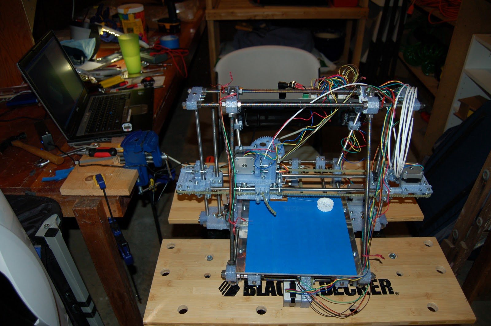 |
| After: Finished Mendel with first print (and build devastation in workshop) |
Adventures in 3-D Printing
This blog is intended to document the various trials and tribulations I experience as I experiment with 3-D printing. I have built an open-source 3-D printer called a Mendel, see more here. It's built with Generation-6 electronics from Mendel-Parts, a single controller board that controls all the stepper motors and extruder.
The extruder is the latest geared stepper motor driven extruder but using drive gears printed on a commercial 3-D printer, also from Mendel-Parts.
The extruder is the latest geared stepper motor driven extruder but using drive gears printed on a commercial 3-D printer, also from Mendel-Parts.
Subscribe to:
Comments (Atom)